Using High Temperature Electronics for Distributed Controls of Turbine Engines
The transformation of turbine engine control systems from centralized to distributed architecture is both necessary and enabling for future aeropropulsion applications. Positioning of control electronics in the harsh, high temperature proximity of engine actuators is mandatory for successful implementation of a distributed architecture. High temperature electronics have been the "show stopper" in past attempts due to lack of available parts to make a complete distributed node, cost of solutions, and poor performance of non-volatile memory at high temperature. However, current siliconon- insulator (SOI) wafer fabrication has progressed to a stage that warrants fabricating a new generation of lower cost, temperature-tolerant electronic components to fill this technology gap.
Turbine engine performance has historically been determined by aero-mechanical innovations. Control systems, although critical to engine operation, have been designed to implement engine functionality rather than be a driving force behind their performance. This is a result of the natural incremental progression of technology which has seen controls evolve from complex mechanisms to the present day Full Authority Digital Engine Control (FADEC). Typically, each engine is equipped with two computers (in case one breaks) and these computers communicate to the aircraft computers to fly the plane. In current production engines which leverages the substantial gains observed in the electronics and information processing technology industries outside of aeronautics. Moving from centralized engine control architecture to a distributed architecture will be both necessary and enabling for future aero engine design, providing numerous benefits.
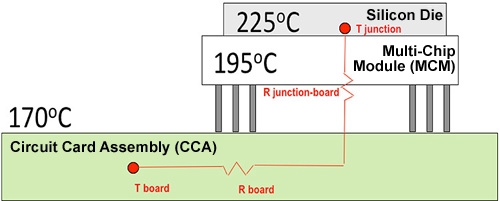
Why are 225°C Parts Needed?
- To survive an environment of 170°C, high temperature electronics need to
survive a junction temperature of 225°C.
- With an ambient environment of 170°C (which is the limit imposed by the use of elastomers and aluminum) there are multiple temperature increases until you reach the silicon die temperature.
- The first delta is the thermal resistance between the Circuit Card Assembly (CCA) and the Multi-Chip Module (MCM).
- The second delta is the thermal resistance between the MCM and the actual silicon die.
- The power dissipated by the actual electronic device
What are the Requirements?
- HT Capability
- Max continuous operating temperature - 150°C?
- Transient excursion - 200°C?
- Junction temperature - 225°C?
Why do we need the HT controls capability (what are the benefits)?
- Operational cost reduction?
- Thermal management due to operational environments?
- Obsolescence mitigation?
- Lower certification costs?
Milestones
- Progress